


Authors
Ruth-Kristina Magh1, Sharath Shyamappa Paligi2
Author affiliations/Institutions
1 Terrestrial Ecohydrology, Institute of Geoscience, Friedrich Schiller University, Jena, Germany
2Plant Ecology and ecosystems research, Albrecht von Haller Institute for Plant Sciences, University of Göttingen, Germany
Overview
The microtensiometer continuously measures in situ water potential of xylem in woody tissues such as stem, branch, and root water potential1,2. This allows for the observation of diurnal cycles of water potential and the recording of environmental influences on water potential in real-time3,4. Standard techniques, such as obtaining leaf water potential using a pressure chamber, do not allow for continuous recording and requires destructive sampling. Other methods, such as microvoltmeters or psychrometers, are either less suitable for continuous measurements in the forest or are very expensive and require significant expertise for installation.
Background
The measurement principle of the microtensiometer is based on the same concept as traditional tensiometers, where liquid water is coupled to vapor via a wettable membrane5. The novelty of this technique lies in the size and type of membrane. The sensor is small enough to avoid significantly disturbing the integrity of the sample tree, and the membrane is made of silicon rather than ceramic. This allows the sensor to reliably measure a wide range of potentials down to -4 MPa1.
Materials/Equipment
The described procedure is based on microtensiometers (Florapulse, Davis, CA, USA) recorded with a CR1000 datalogger (Campbell Scientific, Logan, UT, USA). The installation kit provided by the manufacturer includes:
- the analogue sensor (or the analogue sensor with a SDI12 converter) and cable,
- the packing list with the offsets and multiplier information of each sensor to program the logger,
- a sleeve and cap,
- the drill bit, mating compound, and grease,
- a wire cutter, a spatula, and insulation foil,
In addition, you need to bring:
- a bark depth gauge or a screwdriver/chisel and a calliper,
- a cordless drill and a Forstner drill bit in case of species with thick bark,
- a hammer,
- a torch or phone torch,
- cable ties (depending on the stem thickness adjust the amount),
- napkins and gloves,
- silicon and silicon gun,
Units, terms, definitions
Stem water potential is measured in bar and can be converted to MPa.
Procedure
For correct installation some preparatory steps should be taken with thick barked species or old individuals:
- Measure bark depth using either a bark depth gauge or another tool (such as a screwdriver or chisel). Depending on the species this is crucial to ensure sensor installation into the xylem just below the cambium (i.e. high importance for ring-porous species). To ensure correct positioning, one needs to measure the depths of the “nails” plus the threaded part until the step change (see Figure 1) which needs to sit in the Xylem. Then measure from the step change point until the “venthole” (Fig. 1), if that length is larger than the bark depth one needs to take off exceeding bark using e.g. a Forstner drill bit (see step 2)
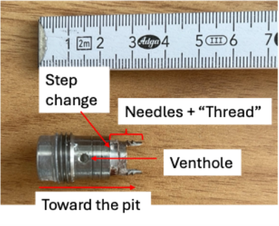
Figure 1. Installation sleeve with marked step change and venthole.
- Prepare the installation site. Fig. 3a shows a prepped installation site in an ash tree individual. We needed to take off a substantial amount of bark using a Forstner drill bit to be able to install the sensor at the correct depth into the xylem.
Subsequently the installation guide provided by the manufacturer should be followed (see link below, they also provide a video): - Pick a site that looks healthy, with a flat surface, check if there are any signs of branching.
- Unscrew cap from sleeve and push it into the installation site with the vent hole facing up.
- Hammer sleeve into the wood until it does not penetrate any deeper indicating it is sitting in the xylem. The figure depicts the correct installation depth. Make sure it sits tight and does not come loose upon contact. Make sure the vent hole is visible, so mating compound can escape the vent hole upon filling. If not visible abandon the installation site and adjust the installation according to step 1 and 2.


- Use the drill bit provided by the manufacturer and drill into the sleeve in steps of 2-3 mm at a time (to ensure xylem is not damaged) and remove wood shaving using the spatula. The the so exposed xylem should look flat, even and not discoloured. Use light source to ensure this e.g. mobile torch. Abandon the install site if the xylem looks damaged or discoloured (e.g. spotted).
- Fill sleeve with mating compound from the back forward to avoid air bubbles.
- Remove the sensor from the capsule and place it into the sleeve right away. THE SENSOR DRIES OUT WITHIN MINUTES SO MOVE QUICKLY!
- Cap the sensor into the installation site by capping the spring into the sleeve (see installation guide provided by the manufacturer for better visualisation). Let the spring force the sensor into the hole towards the xylem, do not use your hands to force the sensor in.
- Clean off excess mating compound with napkins and spatula.
- Add grease over the vent hole and around the sleeve to seal.
- Optional: protect the installation site from stemflow infiltration e.g. create a roof like structure using waterproof silicon (Figure 3b).
- Zip tie probe wire to the trunk to protect the probe from being yanked out.
- Zip tie the bubble wrap insulation around the trunk, take care that in wetter climates the insulation is tied only loosely so that excess water can evaporate. In warmer climates tightly zip tie the insulation foil above and below the install site (Figure 3c).
- Connect the sensor to the datalogger. If using campbell loggers, example program codes are provided from the manufacturer’s homepage (see link below).


Figure 3. Pictorial documentation showing a.) installation site prepared with forstner drill bit to remove excess bark, b.) installed microtensiometer (Florapulse) on the tree with a protective rain shield above (white silicon) to prevent stem flow from infiltrating the installation site, c.) insulation of the installation site with aluminium foil using the zip ties and also securing the cables on the tree to prevent accidental pulling of the sensor.
Notes and troubleshooting tips
- Datalogger programming
Logger programs are available from the provider (see link below). Adapting those ensures measuring correct data.
- Shielding the installation
After few days of installation, due to rain, it is possible that the installation site is flooded by water, so it is recommended to protect the installation site from flooding, e.g., shielding the installation site from stemflow by building a “roof” using silicon as in Fig. 2b. However, in some species, the sensor could be flooded due to sap from phloem as a wounding response, in that case, the sensor needs to be reinstalled.
- Re-greasing
If data values read drier than expected adding more grease to the installation site can help fix that issue. It captures the moisture in the installation.
- Uninstallation, calibration and reusing of sensors
Ideally, the sensors could be removed and reused for installation in the next season or on other trees. For this, the sensor needs to be carefully pulled out and immediately put in distilled water. The sensor should be cleaned using distilled water following the tutorial provided by the manufacturer. In case, the response of the sensors is slow, they can be carefully ground off using sanding sticks (see below) and their performance tested again. Note: if the temperatures go below freezing point, the sensors must be uninstalled to prevent them from cavitating
5. Reusing SDI12 with new analogue sensors
After using the sensor for a long time, it is possible they break, cavitate or it becomes difficult to uninstall the probe without damage. In such cases, we could ideally still reuse the SDI12 convertor of the broken sensor together with a functional/new analogue probe. However, theSDI12 converter should be reconfigured with appropriate calibration settings provided by the manufacturer for that particular probe. The description by the manufacturer is however not straightforward, so we added a description of the procedure here using a CR1000 Logger, and Loggernet by Campbell Sci (see below). We recommend using SDI12 for long cable extensions (e.g. installation in the canopy or at large distance) and analogue direct logger connections for immediate logger vicinity locations.
In order to re-program the SDI12 converter you need:
- The packing list with the calibration values of each sensor
- A data logger (e.g. CR300, CR1000, CR1000X)
- A terminal emulator (e.g. using Loggernet, Campbell Sci)
- Connect the sensor to the SDI12 converter and connect both to the Logger (Note: for this, it is important no other sensor is connected to the same channel on the data logger)
- Open the terminal emulator and direct to the respective channel
- Identify the sensor address and use the commands provided in the table to change the calibration, in this case we use the calibration values provided in Fig. 3 for sensor no. A032. The sensor address precedes the respective command.
- Proceed in this manner until all sensors and SDI12 converters are reprogrammed.
Table 1 SDI12 commands and calibration values to be set upon reconfiguration of a SDI12 converter.
| SDI12 command | Value to set | Example A032 |
| XB | mp | -4.5039 |
| XC | mpt | -0.001034 |
| XD | bpt | -0.76 |
| XE | mt | 0.387 |
| XF | bt | -3.43 |


Figure 4. Calibration values provided by the manufacturer for Sensor No. A032
Example: in the example provided in Fig. 5 we used the terminal emulator to identify and reprogram a SDI12 converter to the sensor calibration values of the sensor A032 (see above). The SDI12 address of the sensor is “j”. The commands “jMC!” and subsequent “jD0!” request the sensor to take a measurement and respond with its address, the water potential in bar, a direct reading of the sensor in mV/V, the resistance of the onboard thermometer in Ohms and a 3-character checksum (see also manufacturers homepage).
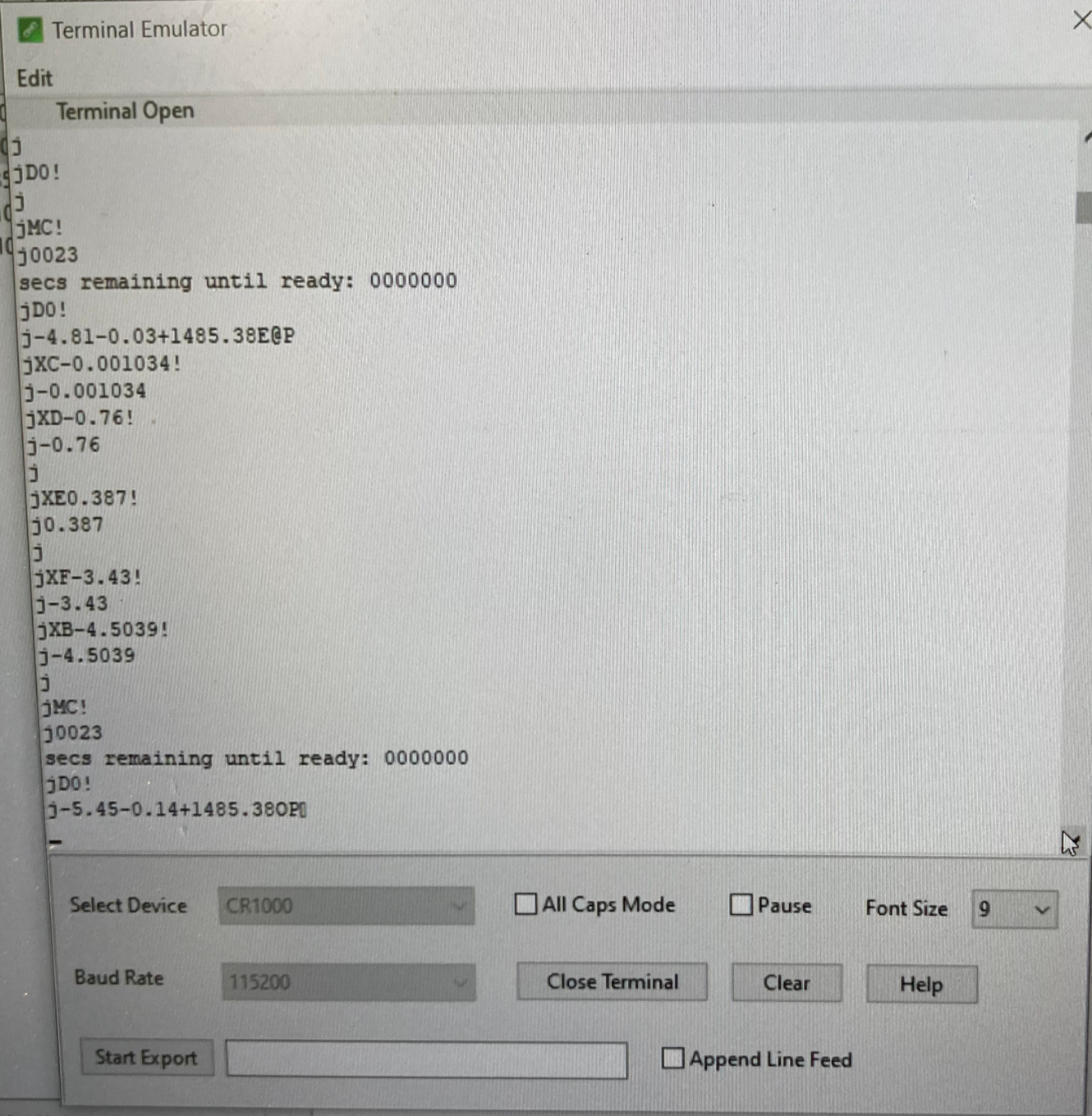

Figure 5. Example of reprogramming a SDI12 converter with the calibration values provided in table 1. The SDI12 address for this sensor is “j”.
Links to resources and suppliers
- Florapulse Homepage (see Resources for the datalogger programs)
- Campbell Scientific
- Sanding sticks
Literature references
- Pagay, V. et al. A microtensiometer capable of measuring water potentials below −10 MPa. Lab. Chip 14, 2806–2817 (2014).
- Blanco, V. & Kalcsits, L. Microtensiometers Accurately Measure Stem Water Potential in Woody Perennials. Plants 10, 2780 (2021).
- Lakso, A. N. et al. A microtensiometer sensor to continuously monitor stem water potentials in woody plants – design and field testing. Acta Hortic. 317–324 (2022) doi:10.17660/ActaHortic.2022.1335.39.
- Pagay, V. Evaluating a novel microtensiometer for continuous trunk water potential measurements in field-grown irrigated grapevines. Irrig. Sci. 40, 45–54 (2022).
- Durner, W. & Or, D. Soil Water Potential Measurement. in Encyclopedia of Hydrological Sciences (eds. Anderson, M. G. & McDonnell, J. J.) (Wiley, 2005). doi:10.1002/0470848944.hsa077a.
Health, safety & hazardous waste disposal considerations
Secure the cables e.g. using zip ties to avoid stumbling and falling onsite (e.g. Figure 3c). Carry extra tissues with you to clean the installation site from excess mating compound.
Please consider the environment and take your rubbish with you!
Search terms and classification
This protocol has been tested on the following forest tree species in a temperate climate (Germany, Central Europe):
Fagus sylvatica
Fraxinus excelsior
Carpinus betulus
Tilia cordata
Acer platanoides