 Protocol
Authors
Margaret McCully 1 and Martin Canny 2
Author affiliations
1Division of Plant Industry, CSIRO, Canberra, Act 2601, Australia
2Plant Science Division, Research School of Biology, RN Robertson Building, The Australian National University, Canberra, ACT, Australia 0200
Background
The elusive goal of botanical microscopy is to visualize plant structures, from organs to cells, in their real functioning mode in the intact plant.
Improvement in methods of specimen preparation (use of fresh tissues, chemical fixations and embedments) which better preserve cytoplasm, organelles and macromolecules, and which reduce tissue distortion for use with either simple or sophisticated instrumentation, has greatly enhanced the ability of microscopists to obtain physical and molecular insight into how plants function. Important as these advances in specimen preparation are, they do not allow plant biologists to address the basic fact that functioning plants are comprised mainly of water and soluble nutrients, and that most or these vital components are lost during all conventional preparative treatment, leaving the roughly 10-15% of plant component composed of macromolecules that are immobilized by chemical fixation, and not extracted during preparation by dehydration and/or solvent and resin monomers.
To date, the only way to immobilize water and soluble components in situ, and to preserve the location of inherent gas and water-filled spaces and tissue dimensions as they were in the living intact plant, is by cryo-fixation. The simplest (and most informative way) to observe these specimens is in an SEM equipped with a cryo-stage (CSEM) which maintains the inherently- hydrated specimen at LN2 temperature during observation. Scanning electron microscopes reveal either surface features of intact whole mounts or anatomical details of internal surfaces produced by fracturing or cryo-planing the frozen specimens.
Because organs, cells and tissues can be viewed undistorted, unextracted and in their inherent state of hydration, and in situ, the CSEM has produced a wide spectrum of newly revealed plant properties ranging from the inherent structure of surface waxes, daily embolisms and refilling of xylem conduits in plants in the field, the first accurate measurements of dimensions of guard cells and stomatal apertures in transpiring plants, phase transition in plant mucilages, to observations of crop roots and associated microbes and soil fauna in situ in deep biopores in the field.
CSEM combined with energy dispersive X-ray microanalysis
Combining CSEM with quantitative energy dispersive X-ray microanalysis of the cryo-fixed specimens (CEDX) allows cell-specific localization of elements heavier than atomic number four (depending on concentration and the type of detector available). With suitable preparations and standards the elements can be quantified, thus greatly extending the possibility of linking specific structure with function. The most fundamental general observation that has been revealed by this technique is marked heterogeneity of element type (both essential and toxic) and their concentrations, not only in specific tissues, but even in adjacent cells (apparently structurally identical) within the same tissue. These observations raise basic questions regarding mechanisms directing this heterogeneous patterning, and its significance in many important functions including tolerance of salinity and toxic elements, xylem function, fungal control of phosphorus release in mycorrhizal roots, and the role of silicon in plant function.
Advances in the understanding of plant function achieved so far, and possibilities for further fruitful use of CSEM and CEDX are reviewed in McCully et al. (2009, 2010)
Technical background
Detailed information on background, and references for the techniques used in our standard protocol below, are given in the Appendix of McCully et al. (2010) (Available at http://www.publish.csiro.au/paper/FP10095.htm![]() ). Included are sections on cryo-fixation, specimen preparation for analysis, cryo-planing, etching, specimen coating, the sampling problem, element quantitation, achieving the most useful information, and limitations of CEDX Here we outline some highlights from this information.
). Included are sections on cryo-fixation, specimen preparation for analysis, cryo-planing, etching, specimen coating, the sampling problem, element quantitation, achieving the most useful information, and limitations of CEDX Here we outline some highlights from this information.
Cryo-fixation
Cryo-microscopists have emphasized the importance of very rapid freezing which produces no ice crystals in specimens. While this vitrification is desirable for retention of maximum fine cellular detail, it can be realized only with minute tissue pieces since, at best, it is attained only within a few μm from the specimen surface. Cutting out such small pieces for freezing is clearly not compatible with obtaining specimens from intact, functioning plants. If plant parts must be severed before freezing, it is important to consider that liquids will have been displaced, and wound responses may have occurred. Most intact plant parts are too large to be frozen quickly. The ice crystals formed will commonly be a few micrometres wide, with layers of the solutes sequestered between them (eutectics).These patterns are useful in structural studies since they indicate the presence of solutes and they are usually absent in senescing or dead cells.
Since the ice crystals are confined within cell compartments, their presence is not a limitation for quantitative CEDX so long as the X-rays are collected from an area that covers most of the vacuole or other compartment being analysed. This has been shown by analyses of known solutions loaded into empty vessels in the interior of roots. Those experiments have also shown no significant variation from the known solute concentration of the infusing solutions and their within-vessel CEDX analyses following freezing with a range of common cryogens.
Cryo-planing
The importance of cryo-planing to produce a smooth face for CEDX analysis cannot be overemphasized. Surfaces with irregular topography result in scattering of incident electrons, obscuring of induced X-rays by surface hills and valleys, and spurious X-rays which distort the emission spectrum. Goldstein et al. summarize the problem: – Rough surfaces represent the greatest challenge to quantitative XR microanalysis’.
Interior, smoothly planed surfaces in any desired plane are excellent for tissue structural investigations. They also have the great advantage that they can be returned to the cryo- microtome repeatedly and replaned, making serial observations possible.
Specimen coating
Metal (or carbon ) coating of specimens is essential to prevent charge buildup, which obscures regions of the specimen and distorts analysis. The usual coatings for structural studies (gold, platinum etc) are unsuitable for specimens to be analyses because, a) elements may be differentially sublimed by the high heat required for coating these metals; and b) these coatings differentially absorb emitted X-rays of different energy. Only three elements are suitable for X-Ray analysis, Al, Cr and C, and of these, Al has the least distortion of the X-ray spectrum.
Our standard protocols for cryoSEM for structural analysis (CSEM), and for energy dispersive X-ray microanalysis (CEDX)
This protocol for CEDX is published as Accessory Material ( 10.1071/FP10095_AC ) with McCully et al. (2010) and is included here with permission from CSIRO Publishing. In sections 1 to 7 most of the methods apply to specimen treatment for both structural and analytical investigations, but we have added additional information that is applicable only to structural studies. These additional procedures are indicated in italics. From sections 7 onward the information only applies to CEDX .
- Preliminary study – Before beginning any CSEM or CEDX analysis of unfamiliar material we do preliminary optical microscopy of the region of interest. Hand-cut sections and even thin sections of embedded tissues help in selecting and interpreting SEM images of the desired region. A thorough understanding of the tissue architecture saves both time and money particularly when doing analysis.
- Selection of material – Ensure that the samples are representative of the conditions for which you want the observations and/or analyses (e.g. from well-watered, or desiccating plants in the field, or seedlings in a Petri dish).
- Cryo-fixation – Freeze the desired regions with liquid nitrogen (LN2), or cryo-pliers (Fig. S1) cooled with LN2, disturbing the functioning plant as little as possible. Remove the frozen pieces and store at LN2 temperature till used. (Frozen samples can be transported long distances in a “dry shipper” at LN2 temperature).
For morphological study of external features, frozen pieces can be mounted on appropriate stubs (Fig. S2) and transferred to the cryo-preparation stage. For delicate specimens, fresh material can be mounted and frozen directly in the cryo-preparation chamber (Craig and Beaton 1996).
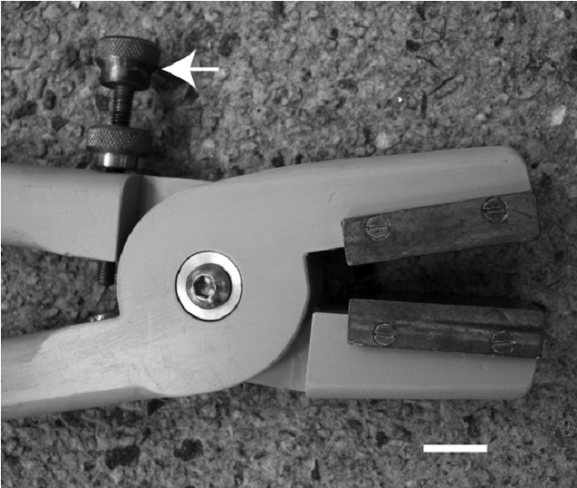
Fig. S1. Purpose-made cryo-pliers with thick, polished copper jaws. The spacing between the jaws is adjustable with the screw system (arrow) to accommodate specimens of different thickness. Bar = 10 mm. - Cryo-planing – A smoothly planed face is essential for accurate quantitation. Trim frozen tissue to ~2 mm lengths under LN2. Place cryo-glue on an appropriate Al stub (Fig. S2a) and quickly remove the sample from the LN2 using cooled forceps, orient it in the glue and re-freeze immediately. Transfer the stub and specimen in LN2 to a cryo-microtome. Plane to a smooth face in the desired plane at ~ -90∘C (the optimum temperature can vary with the nature of your material, e.g. presence of oils and resins will require a lower temperature). For the initial -rough’ planing the sections cut (and discarded) can be relatively thick (ca. 0.5 – 0.2 μm) with cutting speeds 1-1.5 mm/sec. For final polishing of the face much slower speeds are used (e.g. 0.3 mm/sec) and only thin (60-80 nm) slices removed. Particularly during this slow final polishing, it is important to watch the specimen face carefully and gently remove any debris that accumulates on the face or the knife edge. A fine sable-hair brush must be used. If debris is accumulating in spaces in the tissue at the block face, an anti-static gun used during cutting may help. Glass knives are used to trim to the desired plane, and for many specimens glass-planed surfaces are satisfactory, but for hard specimens a diamond knife may be necessary for the final polishing. Planed specimens can be stored in LN2 or used immediately.
Cryo-planed samples are ideal for study of internal structure. To reveal three dimensional structure it may be useful to expose the interior of frozen pieces by fracture in the cryo-preparation chamber of the microscope.

Fig. S2. Purpose-made hardware for handling frozen specimens
a) Aluminium stubs that can accommodate a variety of specimen sizes for either transverse or longitudinal fracturing or planing and viewing. Stubs fit into the cryo-microtome chuck, and into the holes in the adapters in (b). Bar = 6 mm.
b) Adapters that accommodate cryo-specimens and slot into the microscope cryo-stage. The one on the left is for whole mounts, the others have holes for two or four stubs, each secured by a grub screw (arrowheads). The small hole at the top end of the middle adapter can hold a standard. Each adapter accommodates the rod of the cryo-transfer device in a threaded hole in one end (arrows). Stubs with the frozen, planed specimens are inserted into the adapters under LN2. Bar = 6 mm.
c, d) The mount (c) for the adapters (b), is slanted upwards so that the cryo-transfer rod clears the edge of the LN2 bath, for threading into the adapter (b, d). The specimens can then be transferred to the CSEM. Bars c) and d) are 6 and 10 mm respectively. - Transfer to the microscope – Remove the stub with its planed sample from the microtome and quickly affix it in place on a stage adapter (Fig. S2b) under LN2. Slide the adapter into the sloped mount (Fig. S2c, d) under LN2. Attach the rod of the cryo-transfer apparatus to the adapter and quickly move it to the SEM preparation chamber and thence to the cold stage. During transfers avoid exposure of specimens to air as much as possible.
- Etching – While watching the specimen at 1 kV, etch at -90∘C till cell outlines are barely detectable. Some parts of a complex plant tissue etch faster than others. The judgement of etching progress is personal and subjective and should be done by a practised operator constantly watching the loss of ice, varying the area observed, and the magnification. Etching at -90∘C should not last longer than about 3 min. Over-etched specimens cannot be used for accurate quantitation. The observer is aiming for the minimum change compatible with certain knowledge of the anatomy of the specimen. When the cell outlines have just appeared the heater is turned off and the stage is cooled rapidly to -160∘C by increasing the flow of LN2, and the specimen returned to the preparation chamber.
Etching is also essential for all specimens used for structural study to remove any frost formed during specimen preparation. For cryo-planed samples remove just enough of the surface ice to reveal the cells and their contents. For 3-D observations of fungal hyphae within cells of cryo-planed specimens, deep etching is appropriate (Refshauge et al. 2006). - Coating – Appropriate coating of the specimen is also necessary for accurate quantitation. We use Al (or C for Al quantitation). Coating with Al is also an art that needs practice, maintaining the right current through the heating coil for the right time, while the specimen is moved about in the Al shower. This usually needs two operators. It may be necessary to modify the commercial evaporator in the cryo-preparation chamber, with a spiral of resistance wire to hold a rolled piece of high purity Al foil of predetermined mass. To get a shiny mirror coating with Al requires a higher vacuum than normally available in the conventional preparation chamber. A turbo pump should be fitted to the chamber to attain at least 10-6 Torr.
Gold, gold palladium or platinum coating is used for structural work but these metals are unsuitable for CEDX analysis. - Microscope settings recommended for CEDX analysis –
a) Choose an appropriate accelerating voltage. It needs to be high enough to excite X-ray lines for the elements you are interested in observing. We use 15 kV.
b) Use the working distance as dictated by your EDS geometry. This information should be provided by your EDS manufacturer. For our detector for example this is 15.3 mm.
c) It is important to use an instrument with good beam stability. Maintain a fixed beam current; if possible measure this using a Faraday cup and a nano-ammeter. Check regularly during your session to ensure the chosen value is maintained. Any change in this value will translate into changes in measured X-ray intensities that are independent of any element concentration you are trying to measure. We use a probe current of 300 pA.
d) Maintain a cobalt, copper or nickel standard in the chamber. These all emit low (-L’ lines) and high energy (-K’ lines) X-rays which are useful for checking for drift in the offset and gain settings of the spectrometer. Your software will probably provide a calibration routine for this purpose. It’s a good idea to check the settings at the start of each day. - Collecting spectra –
a) Count for a fixed live time (e.g., 100 s).
b) Make sure the sample is not charging when collecting X-ray data, otherwise the measured intensities can be severely in error. You may need to recoat the sample.
c) Collect spectra using raster dimensions that cover the tissue compartment that you want to analyse (e.g. vacuole, cytoplasm, wall, nucleus, plastid, vessel lumen) without overlap of adjoining compartments. This will eliminate error due to the heterogeneity caused by ice crystals and sequestered solutes, by giving a mean reading for the whole compartment. - Quantitation – The use of frozen standards is critical for accurate quantification.
We include 5% colloidal graphite in the standard solutions. Because the signal received from one element is influenced by the presence of other elements, the calibration solutions contain the same molarities of Na, Mg, P, S, Cl, K. Thus a series of solutions is made up, each of all these elements together at 0 mM, 12.5 mM, 25 mM, 50 mM, 100 mM, 300 mM, 500 mM, and the one series of measurements provides calibration curves for all these elements. Convex drops of each thoroughly-mixed solution (use a vortex mixer) are quickly set over holes in stubs individually and immediately frozen in liquid ethane. The convex drops are planed, etched, and coated identically to the specimens.
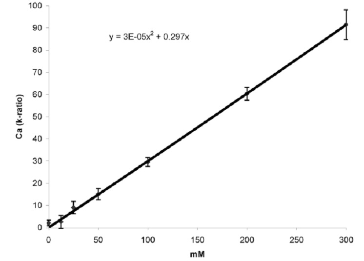
We collect 10 spectra per drop, using the same instrument parameters for the standards and the unknown tissue specimens. Peak intensities are determined by either using the net integrated counts for each of the peaks of interest or alternatively it may also be possible to derive a parameter known as the k-ratio for each of the elements of interest depending on your software. The k-ratio, defined as k = Iunknown/Istandard, is simply a scaled version of the above-mentioned net integrated counts. The advantage of using k-ratios over using net integrated counts is that peak fitting as well as background removal routines are sometimes more sophisticated when using the k-ratio approach (depending on your software). This leads to more accurate estimates of (relative) peak intensities. A sample calibration curve relating k-ratios to [Ca] in the standards is given in Fig. S3. In our experience the calibration curves for each element are linear only up to 300 mM. The 500 mM points usually fall below the projected line, and we do not claim the same accuracy for concentrations above 300 mM. Once prepared, unplaned frozen standard drops can be stored indefinitely in a cryo-store, and planed and processed later as required. Repeat calibrations are done about twice yearly.

Fig. S3. A typical calibration curve for quantification relating k ratio to [Ca] in a cryo-planed and Al-coated carbon-slurry standard.

Example images
Please formally request permission from Dr. Margaret McCully before reproducing these images, except for teaching purposes.

Example 1: A stigma of white cockle (Silene alba) frozen directly in the preparation chamber of the microscope.

Example 2: A cryo-planed transverse face of the stele and part of the aerenchyma of a root of water hyacinth (Eichornia crassipes) frozen with cryo-pliers while attached to the plant. This prepartion is not only excellent for the preservation of delicate anatomy and flooded air spaces. but its flat face is also suitable for quantitative CEDX.

Example 3: Emerging root hairs at the tip of a root of canola (Brassica napus) frozen directly as the young root extended through the soil. Note droplets of exudate on several root hair tips.
Literature References
Craig S, Beaton CD (1996) A simple cryo-SEM method for delicate plant tissues. Journal of Microscopy 182, 102-105
Goldstein et al. (2003) Scanning Electron Microscopy and X-ray Microanalysis. 3rd Edn. Springer-Verlag: Berlin.
McCully ME et al. (2009) Cryo-scanning electron microscopy (CSEM) in the advancement of functional plant biology: morphological and anatomical applications. Functional Plant Biology 36, 97-124.
McCully ME et al. (2010) Cryo-scanning electron microscopy (CSEM) in the advancement of functional plant biology: energy dispersive X-ray microanalysis (CEDX) applications. Functional Plant Biology 37, 1011-1040.
Available at: http://www.publish.csiro.au/paper/FP10095.htm![]()
Refshauge S, Watt M, McCully ME, Huang CX (2006) Frozen in time: a new method using cryo-scanning electron microscopy to visualize root-fungal interactions. New Phytologist 172, 369-374. doi: 10.1111/j.1469-8137.